Patchbays Made Simple
August 15, 2021 · Sam Fisher
If you’re not prepared for what you’re looking at, patchbays could be very confusing.
This article will breakdown patchbays into simplest form. No mattter what .
Do I Need to Know About Patchbays?
For a producer or engineer using analog equipment, absolutely.
For live sound engineers, It may not be considered “essential”.
However, many will tell you how much the knowledge will elevate your growth.
Let’s break down the basics.
What is a Patchbay?
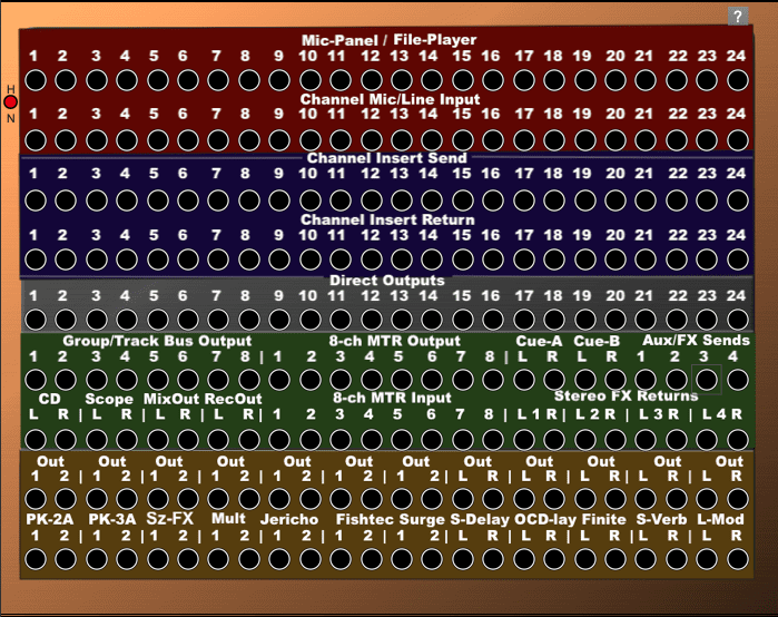
The routing matrix of an analog mixing setup. The patch points represent all the inputs and outputs in the environment that we could route signals to and from using patch cables. This enables engineers to incorporate other hardware devices into the mixing signal chain.
Consideration – Outputs Over Inputs
Majority of the time, the patch points will tend to have the OUTPUTS positioned above the INPUTS.
This is important when considering the next section.
Patchbay Normaling
It’s helpful to patch and route using the front end of the patchbay. Even more so, it’s intuitive to wire default processes connected through the backend of the patchbay. This opens up real-estate visibility from cables on the front. The flexibility of combining front-end and back-end connections is called “Normalling”
Fully Normalled
A fully-normalled patchbay configuration is used to create a connection between two devices while leaving a point of entry for interception from another device. Without an interception, two devices are connected directly, without the need for a third patch cable for each direct connection. This can quickly clean up a lot of clutter as your setup grows.
With an interception, another device can be quickly inserted into the signal chain. For example, a compressor can quickly be inserted between a console and a computer running Pro Tools just by connecting the compressor to the output of the console and the input of the computer.
Half Normalled
A half-normal patchbay configuration is commonly used with analog line level signals. The signal from the source device, at the top jack, flows through to the jack directly below, to a destination device, via the “half-normal” signal route. This type of normaling differs from a full-normal in that the signal switches off, breaking the normal when patching into the bottom jack only.
This configuration also allows the engineer to create a second signal route, while maintaining the half-normal signal route – In effect, a Y cable. An identical signal is created when patching into the top jack, thus not breaking the normal. The top jack can also be used as a monitor jack, allowing quick checks of the signal without breaking the normal.
Breaking the normal by inserting a patchcord into the bottom jack creates no connection between the vertical pairs of jacks. This “broken normal” state is maintained as long as there is a patchcord in the bottom jack. The signal can then be re-routed, as required, in the signal chain.
When you make a half-normal patchbay connection, you split the signal to two separate inputs. Unlike a full-normal setup, the signal flow isn’t broken when you connect a patch cable to the output. The signal is sent into the input of one device as well as the input of another. This allows you to record a dry and wet signal at the same time.
Non Normalled
Unlike full and half-normal, non-normalling on a patchbay is when the output does not flow down to the corresponding input unless you connect a patch cable. It can be beneficial, particularly in effects processing and feedback loop situations.