Introduction to Patchbays
Background
If you’re not prepared for what you’re looking at, the “Patchbay” is quite confusing and intimidating. They may look scary at first but, there is order to the chaos. Understanding how it works unlocks the full power of signal flow. It offers you the capability of routing audio to and from anywhere in the environment.

What is a Patchbay?
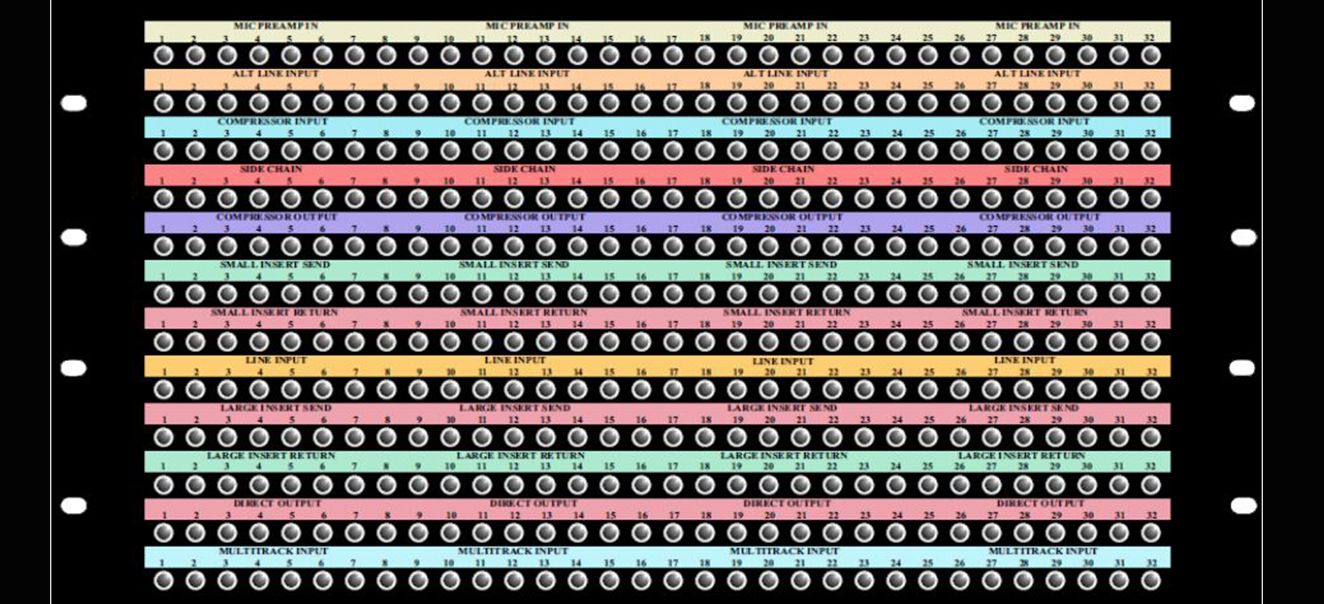
A patchbay might be arranged by row, column or a combination of both.
They all do the same thing. Read the labels!

Do I Need to Know About Patchbays?
For a producer or engineer using analog equipment, absolutely. For live sound engineers, It may not be considered “essential”. However, many will tell you how much the knowledge will elevate your growth. If you work with sound devices in your home studio setup, you will benefit from patchbays.
Listen to Serj from System of a Down talk about patchbays in his home studio.
Patchpoints
The patchbay has access to all the inputs and outputs of devices in an environment. The cables used to route the signals are connected via “patchpoints”. A patchpoint will either be an input or an output indicated by the labelling.

Common Patchpoints
- Microphone panel – (example: signal that comes from the performers booth/room).
- Channel Mic Input – Entry point for signal to flow into the channels on the console.
- Channel Line Input – Entry point for signal to flow into the channels on the console.
- Insert Send – Allow audio from mid-way down the channelstrip to patch in an effect.
- Insert Return – The signal we sent in the section above typically comes back here.
- Direct Outputs – Tap the signal coming out of each channel on the mixer
- Group Outputs – Combine signals to be processed together
- Aux & Cue Sends – Duplicate signals to be used in headphone mixes or time-based fx.
- Stereo Returns – Dual-Input destination for incoming stereo fx
- Audio Effects – Every external audio effect has its own input and out!
- Multitrack Recorder – Patch in and record sound from any destination
The Interception
The hidden component between the microphone and the mixer, the patchbay.
By default, mic-panel slot 8 will feed channel 8 on the mixer.
Using the patchbay, slot 8 could be re-routed to channel 2 on the mixer.
The default behavior we want is that mic-panel slots feed the same channel inputs on the mixer. However, you may wish to reroute the mic-panel slots feeding the mixer by patching a connection on the patchbay. Without any front-end connections on the patchbay, the mic-panel signals will typically default to the mixer via a connection made on the back-end.
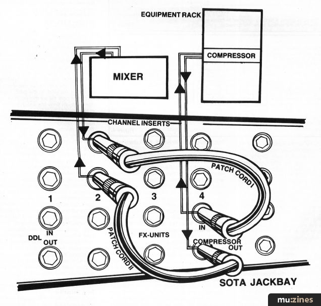
Another device can be quickly inserted into the signal chain. For example, a compressor can quickly be inserted between a the bass and mixer input.
Normaling
Patch and route using the front end of the patchbay. It’s intuitive to wire default processes connected through the backend of the patchbay. This opens up real-estate visibility from cables on the front. The flexibility of combining front-end and back-end connections is called “Normalling”
A Normalled patchbay has vertical pairs of jacks (usually In and Out) where audio automatically flows between the two jacks. – Sweetwater.com
Fully Normalled
A fully-normalled patchbay configuration is used to create a connection between two devices while leaving a point of entry for interception from another device. Without an interception, two devices are connected directly, without the need for a third patch cable for each direct connection. This can quickly clean up a lot of clutter as your setup grows.
Half Normalled
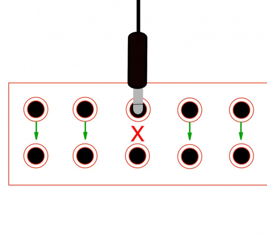
This type of normaling differs from a full-normal in that the signal switches off, breaking the normal when patching into the bottom jack only.
This configuration also allows the engineer to create a second signal route, while maintaining the half-normal signal route – In effect, a Y cable. An identical signal is created when patching into the top jack, thus not breaking the normal. The top jack can also be used as a monitor jack, allowing quick checks of the signal without breaking the normal.
When you make a half-normal patchbay connection, you split the signal to two separate inputs. Unlike a full-normal setup, the signal flow isn’t broken when you connect a patch cable to the output. The signal is sent into the input of one device as well as the input of another. This allows you to record a dry and wet signal at the same time.
Non Normalled
Unlike full and half-normal, non-normalling on a patchbay is when the output does not flow down to the corresponding input unless you connect a patch cable. It can be beneficial, particularly in effects processing and feedback loop situations.
Other Considerations
Outputs Over Inputs
Many times , the patch points will tend to have the OUTPUTS positioned above the INPUTS.
This is important when considering “feedback loops”, something we want to avoid!
Feedback Loop
When a signal is re-introduced to itself it creates an event where the sound is infinitely processing itself. This is similar to when a microphone is placed in front of a speaker. In in most cases it will result in an unwanted sound. In the case of routing with a patchbay will likely cause damage to equipment or someones hearing!